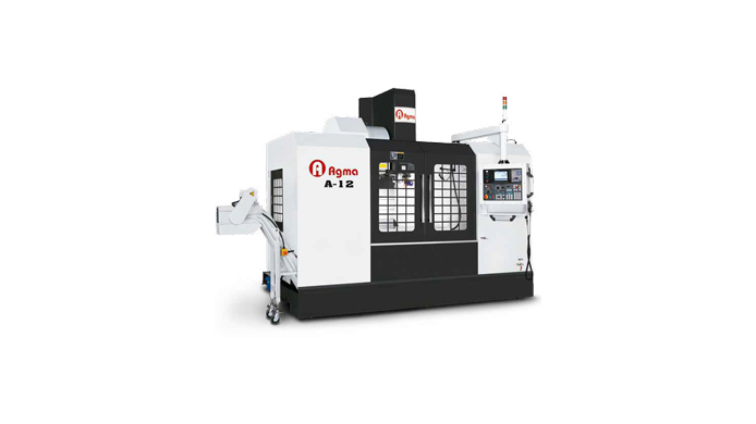
AGMA A-12

All three axes adopt high precision 45mm roller-rail linear guideways and Ø45mm ball screws. A12/A14’s unique four roller-rail linear guide ways with eight sliders on the Y axis enable the ultimate support for high speed and machining accuracy. With Meehanite cast iron across the mach ine structure, machine column and saddle are carefully designed with dual layers casting for the most rigid structure to absorb cutting vibration.

Synchronously Adopt the Advantages of the European & Japanese Design

  • 954mm wide-span rigid column.
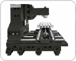
  • Taiwan-made PMI extra-large 45mm precise roller- rail linear guide way.
  • Adopt high-end direct motors and high rigidity couplings in three axes.

Moer Powerful Z-axis Motor7kw (no counter balance design) for BT40.
7kw (with counter balance design) for BT50.

High Reliability and High Accuracy for Ballscrew DesignØ45mm Pitch 12 C3 ball screw with high class double nut provides strong rigidity, high torque, better accuracy, longlife, and effectively heat extension control.

Stable Air Supply EquipmentThe gas storage barrel assists to acquire steady air source to increase equipment utility rate.


Design with More Sliders and More Stable Support for X, Y, and Z axisX & Z axes adopt 45mm width roller-rail linear guide ways including 2 tracks, and each track has 3 sliders (total 6 sliders) Y axis adopts 45mm width roller-rail linear guide ways, 4 tracks, each track with 2 sliders (total 8 sliders)


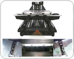
Design with More Screw-Type Chip Augers for Y axisscrew-type chip augers on Y axis to increase the chip removable capacity.


Enlarge Saddle Pads to Enhance the Support for the Table.


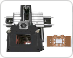
Box-Type Dual-Layers Casting ColumnThe unique column design achieves the ultra-excellent rigidity to minimize cutting induced vibration and deformation.


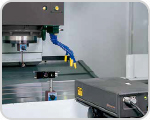
Calibration with Laser Interferometer was Performed and CertifiedAgma conduct 100% inspection to full travel length of three axes. Standard VDI 3441 3δis employed to ensure the machine accuracy and righteous of the inspection. For each axis, inspection along full axial travel length backwards and forwards for 6 times is conducted.
Model Unit A-12
Spindle Spindle Taper NO.40/NO.50
Transmission Belt Driven (BT-40)/Belt Driven (BT-50)
Spindle Speed r.p.m. P8000 (BT-40)/P8000 (BT-50)
Spindle Diameter mm 150 (BT-40)/190 (BT-50)
Table Table Size mm 1350 x 700
T-Slot mm 5x18x125
Max. Table Load kgs 1200
Travel & Feedrate X Axis mm 1200
Y Axis mm 700
Z Axis mm 700
Distance from Spindle Nose to Table mm 120 ~ 820
Distance from Spindle Center to Surface of Column Way mm 820
Rapid Traverse (X/Y/Z) M/Min X,Y,Z:32/32/24
Cutting Feedrate mm/min X,Y,Z: 1 ~ 10,000
ATC Tool Shank BT-40/BT-50
Pull Stud MAS P40T-1(45°)/MAS P50T-1(45°)
Magazine Capacity pcs 24
Max. Tool Diameter (Full Storage) mm φ80/φ125(for BT-40)/φ125/φ250 (for BT-50)
Max. Tool Length mm
300
Max. Tool Weight kgs
6 (BT-40)/15 (BT-50)
ATC Type
Arm Type
Motor For Spindle (Cont./30 min) kw 7.5/11(10/15) BT-40/ 11/15(15/20) BT-50
X/Y/Z Axis kw 4 / 4 / 7
Ball screw X Axis (Diameter/Pitch/Accuracy) φ45/P12/C3
Y Axis (Diameter/Pitch/Accuracy) φ45/P12/C3
Z Axis (Diameter/Pitch/Accuracy) φ45/P12/C3
Triaxial Bearings
(Motor End / Bearing End)
35TAC72B/(4/2)
Three axes linear guide way X Axis 45mm Width Roller Linear Guideways / 3 Slider / 2-Track
Y Axis 45mm Width Roller Linear Guideways / 2 Slider / 4-Track
Z Axis 45mm Width Roller Linear Guideways / 3 Slider / 2-Track
Misc. Machine Height mm 3200
Machine Space mm 3600*3350
Machine Weight kgs 8450
Controller
OiMF
Scroll to Top