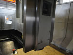
AGMA BDO-2223

BDO-SERIES

High-Rigidity, High-Precision & High-Efficiency Design Concept
HIGH-RIGIDITY

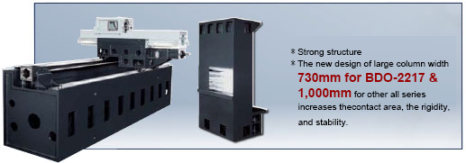
  • The one-piece construction base with modular box design and optimum support maintains the machining accuracy.
  • The construction base with optimum rigidity support design is proved by ultimate analysis that can guarantee maximum loading on worktable and heavy-duty cutting.

HIGH-PRECISION

  • The spindle position is designed with symmetrical to center that provides stability of temperature level. Moreover, the short transmission system design reduces the heat conduction and extends the machine’s life expectancy.
  • X-axis and Y-axis is adopted THK linear roller guide ways.

HIGH HORSEPOWER, HIGH ROTATIONAL SPEED, HIGH STABILITY

  • 35-HP spindle motor, 6,000 RPM two-steps automatic change gear box.
  • Output torque of 642Nm(ZF gear box), offers capability of low-speed heavy cutting and high-speed precision cutting with extensive process range. (For demand of higher torque, please contact with our sales department).

AUTO TOOL CHANGE SYSTEM

  • The Max. cutter diameter is 125mm & the cutter length is 300mm.
  • Auto tool change time is 8 sec. (Tool to Tool)

PROCESS ABILITY

  • Y-axis travel: 1,600mm/2,100mm/2,600mm
  • Z-axis travel: 1,000mm (standard)
  • Z-axis travel: 800mm (option)
  • Width Of Table: 1,500mm/2,000mm/2,500mm

UNIQUE X AXIS TRANSMISSION SYSTEM

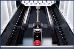
  • Advantage of direct transmission leads that the leadscrew can rotate with no influence from belt tention.
  • Direct transmission with speed-reduction mechanism is added to X-axis to increase the transmission torque, the thrust, and the capacity for workpiece weight.
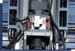
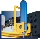
  • Z-axis is adopted oil pressure balance system and building in pressure saver which supports smooth and stability for acting in Z-axis.
  • These three axis motors are adopted direct driven design that provides no back interstices as well as increases the machining efficiency and accuracy.


Double Column Vertical Machining Center
 1. X/Y/Z 1,020/560/510mm ULTIMATE ANALYSIS OF HEAD CONSTRUCTION

    Our head construction has been assayed by ultimate analysis. The strengthened head construction design can reduce deformation risk during machining.


X AXIS TRANSMISSION WAY

    Direct transmission provides the following advantages for the speed reduction mechanism:
  • The ball screw rotates with no influence from belt tenson.
  • The responses of the motor are directly sent to the ball screw.
  • The backlash is minimized.
  • The positioning accuracy is excellent.
  • The torque and the thrust forces are increased.
    *Y-axis gantry adopts modular box-type girdle rip design with the high span linear guide ways supporting. The wide Y-axis design is suitable for big workpiece and chips collection.


Perfect Structure Design High Quality Guarantee

  • Y-axis is adopted modular box girdle construction design with the high span linear guide ways supporting. Therefore, the wide Y-axis is suitable for big items cutting and chips collection.
  • One-piece construction design is Amga’s persist in design concept. High-stability body provides capability for higher accuracy machining. It is not only able to carry a heavy workpiece, but also to perform heavy cutting with the highest-level accuracy in industry.
  • One-piece construction design is Amga’s persist in design concept. High-stability body provides capability for higher accuracy machining. It is not only able to carry a heavy workpiece, but also to perform heavy cutting with the highest-level accuracy in industry.

CHARACTERISTICS OF THERMAL-DEFORMATION COMPENSATION SYSTEM

  • The thermal deformation compensation system includes measurement of thermal deformation, thermal deformation math model developed based on the measured thermal deformation, and compensation card that executes the compensation process. It enhances machining accuracy, solves thermal deformation problem, and increases the cutting accuracy.


THERMAL DEFORMATION COMPENSATION MODEL IS THE ADVANTAGE FOR MOLD MAKING INDUSTRY

  • Spindle & structure thermal deformation compensation
  • Overcome the influence of ambient temperature.
  • Suitable for long machining hours with same accuracy for mold making.
  • The machine can work anytime, no need to warm up the machine in advance.


Different Types Of Spindles Are Available
GEAR- DRIVEN SPINDLE

The gear-driven spindle provides spindle speed of 4,000rpm and 6,000rpm with high output torque which is the best choice for frequent heavy-cutting operations.


ZF SPINDLE

ZF spindle has higher torgue than belt-driven spindle. ZF spindle provides higher rotational speed than gear driven does. ZF gear box has 1:4 speed reduction ratio mechanism. It enlarges output torque by 4 times. It offers an extra choice for users who needs high rotation speed and high torque for machining operation.


CROSS-BEAM BACK HOLDER DESIGN

The design of the back holder of cross-beams neatly aligns hydraulic unit, cooling machines, and spare parts, etc., and meets the requirement of CE regulations. This design offers two advantages:
1. More free spaces for operators
2. Easy to maintain

ITEM / MODEL BDO-2217 BDO-2223 BDO-3217
TRAVEL
X AXIS (WORK TABLE) 2,200mm(86.6″) 2,200mm(86.6″) 3,200mm(125.9″)
2 LINEAR GUIDE WAYS
3*2 SLIDING BLOCKS
2 LINEAR GUIDE WAYS
3*2 SLIDING BLOCKS
2 LINEAR GUIDE WAYS
4*2 SLIDING BLOCKS
Y AXIS (SADDLE) 1,600mm(63″) 2,100mm(82.7″) 1,600mm(63″)
2 LINEAR GUIDE WAYS
2*2 SLIDING BLOCK
2 LINEAR GUIDE WAYS
2*2 SLIDING BLOCK
2 LINEAR GUIDE WAYS
2*2 SLIDING BLOCKS
Z AXIS (HEAD) 1,000mm(39.4″)/
(opt800mm(31.5″))
1,000mm(39.4″)/
(opt800mm(31.5″))
1,000mm(39.4″)/
(opt800mm(31.5″))
2 BOX GUIDE WAYS 2 BOX GUIDE WAYS 2 BOX GUIDE WAYS
DISTANCE FROM SPINDLE NOSE TO TABLE SURFACE 200-1,200mm(7.8″-47.2″)/
(opt200-1,000mm(7.8″-39.4″))
200-1,200mm(7.8″-47.2″)/
(opt200-1,000mm(7.8″-39.4″))
200-1,200mm(7.8″-47.2″)/
(opt200-1,000mm(7.8″-39.4″))
DISTANCE BETWEEN COLUMN 1760mm(69.3″) 2360mm(92.9″) 1760mm(69.3″)
WORK TABLE
TABLE SIZE 2000mm*1500mm
(78.7″*59.1″)
2000mm*2000mm
(78.7″*78.7″)
3000*1500mm
(118.1″*59.1″)
T-SLOT SIZE 7x22mmx200mm 9x22mmx200mm 7x22mmx200mm
DISTANCE FROM TABLE SURFACE TO GROUND 830mm(32.7″) 885mm(34.8″) 830mm(32.7″)
MAX. TABLE LOAD 6,000kgs(13,200lbs) 8,000kgs(17,600lbs) 8,000kgs(17,600lbs)
SPINDLE
SPINDLE TAPER (BT/CAT) BT50/CAT50 BT50/CAT50 BT50/CAT50
SPINDLE SPEED RPM(BT50) 6,000rpm(P & G)(opt.8,000/10,000rpm)
FEED RATE
RAPID TRAVERSE(X/Y/Z) 20/20/10M/Min.
(787/787/393IPM)
20/20/10M/Min.
(787/787/393IPM)
20/20/10M/Min.
(787/787/393IPM)
CUTTING FEEDRATE(X/Y/Z) 1~8000mm/min 1~8000mm/min 1~8000mm/min
MOTOR
SPINDLE BT50 (CONT. /30 MIN.) 22/26kw(30/35HP)  22/26kw(30/35HP)  22/26kw(30/35HP)
AC SERVER MOTOR(X/Y/Z) X,Y,Z:7KW-30NM X,Y,Z:7KW-30NM X,Y,Z:7KW-30NM
COOLANT PUMP 1250W 1250W 1250W
LUBRICATION  PUMP 60W 60W 60W
OIL CIRCULATING COOLANT SYSTEM FOR SPINDLE 1220W 1220W 1220W
ATC
MAGAZINE CAPACITY FOR ARM TYPE 32 TOOL/(OPT.40/60 TOOL)
MAX. TOOL DIAMETER(WITH ADJACENT POCKET EMPTY) BT50-Ø125MM
MAX. TOOL LENGTH 300mm(11.74″)
MAX. TOOL WEIGHT 20Kg(44lbs)
Tool Change Time(T TO T/C TO C) 8/12 SEC.
ACCURACY
POSITIONING ACCURACY ±0.01 mm ±0.01 mm ±0.01 mm
REPEATABILITY ACCURACY ±0.003 mm ±0.003 mm ±0.003 mm
MISC.
AIR PRESSURE 6 Kg / cm² 6 Kg / cm² 6 Kg / cm²
POWER SUPPLY 50KVA, 220V, 3 PHASE, 50/60HZ
MACHINE WEIGHT 26,000kgs(57,200lbs) 28,000kgs(61,600lbs) 28,000kgs(61,600lbs)
MACHINE DIMENSION (L×W×H) 67600*5100*3900mm 67600*6960*3900mm 8530*5100*3900mm
CONTROLLER OiMD/31iMB
Scroll to Top